Distributed training and high-throughput inference workloads are fundamentally bound by the network fabric. While traditional cloud applications rely on asynchronous request-response cycles that absorb latency jitter, distributed deep learning relies on synchronous collective communication. Operations such as All-Reduce, All-Gather, and All-to-All require hundreds or thousands of GPUs to exchange tensors and synchronize at strict barrier points before execution can proceed.
In this execution model, synchronization time is governed by the slowest link in the cluster:
A transient packet drop, an ECMP hash collision, or a millisecond pause on a single switch port stalls every GPU in the collective. As clusters scale from hundreds to tens of thousands of GPUs, network architecture ceases to be an operational detail and becomes the primary determinant of model training efficiency and compute economics.

Scale-Up vs. Scale-Out Fabric Domains
Modern AI supercomputers decouple interconnects into two distinct domains: scale-up (intra-node/intra-rack) and scale-out (inter-node).
Scale-Up: Dense Shared-Memory Interconnects
Scale-up networks connect GPUs within a single node or contiguous rack using proprietary, ultra-high-bandwidth interconnects such as Nvidia NVLink and NVSwitch.
- Bandwidth Density: NVLink 4 delivers 900 GB/s bidirectional bandwidth per H100 GPU, while NVLink 5 on Blackwell architectures scales to 1.8 TB/s per GPU.
- Coherent Memory Space: Multi-GPU systems operate a unified virtual memory space where any GPU can issue load/store instructions directly to remote GPU HBM via load/store semantics, bypassing traditional networking stacks.
- Domain Ceilings: Historically limited to 8-GPU nodes, rack-scale architectures like NVL72 expand the NVLink domain to 72 GPUs across 18 compute trays via liquid-cooled NVSwitch switch planes, delivering 130 TB/s of aggregate bisection bandwidth.
Scale-Out: Leaf-Spine Topologies and Rail Optimization
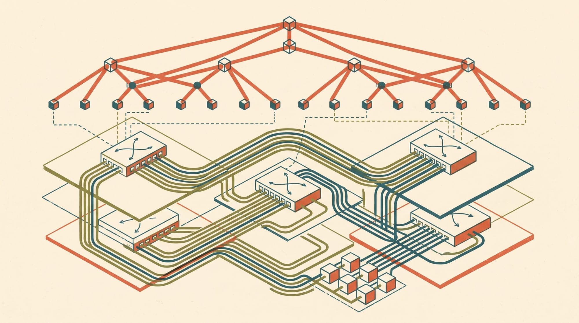
Once communication crosses the scale-up boundary, scale-out networks take over using standard multi-tier Clos (Fat-Tree) fabrics over optical links.
To maximize throughput and prevent cross-traffic interference, production AI clusters implement rail-optimized topologies:
- Rail Mapping: In an 8-GPU node with 8 independent Network Interface Cards (NICs), GPU 0 through GPU 7 are each wired to a distinct network adapter. All GPU 0 adapters across the entire cluster connect to Leaf Switch Plane 0, GPU 1 adapters connect to Leaf Switch Plane 1, and so on.
- Collision Avoidance: Collective operations like All-Reduce typically execute parallel reduction rings across matching GPU ranks. Rail optimization confines these intra-rank data streams to dedicated physical switch planes, preventing different rails from competing for the same spine uplinks.
- Oversubscription: Production training clusters mandate a 1:1 non-blocking bisection bandwidth ratio at every tier, ensuring full line rate regardless of traffic distribution.
InfiniBand: Hardware-Enforced Lossless Fabrics
InfiniBand remains the traditional standard for high-performance AI training due to its native hardware guarantees and low-latency transport design.
Link-Layer Flow Control and Subnet Coordination
Unlike Ethernet, InfiniBand was engineered from its inception as a lossless, credit-based interconnect:
- Credit-Based Flow Control: A transmitting port cannot send data unless the receiving port has explicitly issued buffer credits. This link-level credit management guarantees zero buffer-overflow packet drops under normal operation without needing software retransmissions.
- Centralized Subnet Manager (SM): An active Subnet Manager discovers topology, assigns Local Identifiers (LIDs), and programs forwarding tables across all switches. This eliminates Spanning Tree Protocol overhead and enables deterministic, loop-free routing.
- In-Network Reduction: Technologies such as Nvidia Scalable Hierarchical Aggregation and Reduction Protocol (SHARP) offload collective computations (such as integer and floating-point All-Reduce) directly to switch ASICs. Intermediate switches aggregate gradient tensors in flight, cutting the data volume transmitted back to compute nodes by up to 50%.
InfiniBand Trade-Offs in Production
While InfiniBand NDR (400 Gbps) and XDR (800 Gbps) deliver dependable low latency (sub-microsecond port-to-port) and effective NCCL bus bandwidth exceeding 350 GB/s on 8x H100 systems, they introduce operational constraints:
- Single-Vendor Supply Chain: Hardware availability, firmware, and tooling remain dominated by Nvidia Mellanox ecosystem components.
- Operational Silos: Managing InfiniBand fabrics requires dedicated tooling (
ibnetdiscover,ibdiagnet, OpenSM) that operates outside conventional enterprise Ethernet network monitoring platforms. - Cost Premium: Proprietary optical transceivers, active optical cables (AOCs), and switch ASICs carry higher hardware capital expenditures compared to merchant silicon Ethernet alternatives.
RoCEv2: Engineering Lossless Behavior Over Ethernet
RDMA over Converged Ethernet version 2 (RoCEv2) encapsulates InfiniBand transport packets inside standard UDP/IP datagrams (UDP destination port 4791), allowing RDMA semantics to run over standard Layer 3 Ethernet switches.
Because standard IP networks are lossy by default (dropping packets when switch queues saturate), RoCEv2 requires a dual-mechanism control loop to emulate lossless behavior.
1. Priority Flow Control (PFC)
Defined under IEEE 802.1Qbb, PFC operates at the link layer by dividing physical Ethernet links into 8 virtual traffic classes (priorities).
- Hop-by-Hop Pause: When an ingress switch buffer for an RDMA priority queue exceeds an assigned threshold (), the switch transmits an 802.1Qbb pause frame upstream. The upstream transmitter halts packet transmission on that specific priority queue until receiving an frame or until the pause timer expires.
- Isolation: Non-RDMA traffic (such as storage or control plane traffic) mapped to alternate priorities continues flowing unaffected.
2. Data Center Quantized Congestion Notification (DCQCN)
PFC alone acts only as a reactive emergency brake. If overused, pause frames propagate backward through switch tiers, causing cluster-wide congestion trees. To prevent this, DCQCN provides end-to-end congestion avoidance:
- ECN Marking: When intermediate switch queues reach an early congestion threshold ( to ), the switch sets the Explicit Congestion Notification bits in the IP header (RFC 3168).
- CNP Generation: The destination NIC inspects incoming packets. Upon detecting ECN marks, it generates a Congestion Notification Packet (CNP) and sends it directly back to the source NIC.
- Rate Throttling: Upon receiving a CNP, the source NIC throttles its transmission rate using an internal state machine (multiplicative decrease), followed by a timer- and byte-counter-driven recovery phase (additive increase and hyper-increase).
Operational Failure Modes of RoCEv2
Operating a multi-thousand-GPU RoCEv2 fabric in production reveals several architectural failure modes:
- PFC Deadlocks: In topologies with cyclic buffer dependencies, bidirectional pause frames can form closed dependency loops where Switch A pauses Switch B, which pauses Switch C, which pauses Switch A. Traffic permanently freezes across all participating queues without any packets being dropped.
- PFC Pause Storms: A malfunctioning NIC or misconfigured switch port that continuously transmits pause frames can cascade pause assertions across the entire fabric within milliseconds.
- Head-of-Line (HoL) Blocking: Because PFC pauses an entire priority queue rather than an individual micro-flow, un-congested flows sharing the same priority buffer are penalized.
- ECMP Hash Polarization: Standard Equal-Cost Multi-Path (ECMP) routing hashes packet 5-tuples to select uplinks. In AI workloads characterized by few, massive RDMA "elephant flows", hash collisions frequently map multiple heavy flows onto the same physical link while adjacent links remain underutilized.
- PFC Watchdog Penalties: Switch operating systems deploy PFC watchdogs to detect queues paused beyond a duration threshold and forcibly drain them by dropping packets. However, because standard RoCEv2 relies on Go-Back-N retransmission, dropped packets trigger retransmission timeouts that stall NCCL collectives for hundreds of milliseconds.
Ultra Ethernet Consortium: The Next-Generation Transport Architecture
Recognizing the fundamental limitations of retrofitting lossless requirements onto Ethernet, the Ultra Ethernet Consortium (UEC) released the UEC 1.0 specification to establish an open, purpose-built transport layer: Ultra Ethernet Transport (UET).
UET abandons the fragile requirement for network-wide lossless fabrics in favor of endpoint-managed resilience and fine-grained multi-pathing.
1. Packet Spraying and Out-of-Order Delivery
Traditional RoCEv2 forces all packets of an RDMA queue pair onto a single network path to guarantee in-order packet arrival.
UET removes this restriction:
- Per-Packet Multipathing: Senders spray individual packets of a single transport context across all available ECMP paths simultaneously.
- Elimination of Hash Collisions: Packet spraying evenly saturates every link in the fabric, achieving near 100% bisection utilization without elephant flow polarization.
- Hardware Reassembly: UEC-compliant NICs feature hardware-accelerated reassembly engines that accept packets in any arrival sequence and place payloads directly into GPU memory.
2. Packet Trimming for Fast Congestion Signaling
Instead of relying on coarse PFC pause frames or slow RTT-based feedback loops, UET switches implement packet trimming:
- Payload Truncation: When a switch queue reaches capacity during transient congestion, the switch trims the packet payload and forwards only the header (annotated with congestion metadata) to the destination.
- Immediate Loss Detection: The receiving NIC immediately learns which packet offset was trimmed and returns an explicit selective Negative Acknowledgment (NACK) to the sender.
- Sub-RTT Retransmission: The sender retransmits only the missing packet segment within fractions of a round-trip time, bypassing Go-Back-N delays and avoiding retransmission timeouts entirely.
3. Receiver-Driven Congestion Control
UET shifts rate control authority from sender heuristics to the receiver:
- Credit Grants: Senders request transmission credits; the receiver grants packet transmission windows based on actual arrival rates, queue depths, and end-to-end RTT telemetry.
- Proactive Pacing: By coordinating incoming flows across multiple senders, the receiver prevents incast congestion at its ingress port before switch buffers can fill.
Production Tuning and NCCL Optimization
Achieving high collective throughput across GPU clusters requires tuning both the network fabric switches and host-level communication libraries such as the Nvidia Collective Communications Library (NCCL).
Critical NCCL Runtime Configurations
# Enable GPUDirect RDMA across PCIe and NVLink boundaries
export NCCL_NET_GDR_LEVEL=5
export NCCL_NET_GDR_READ=1

# Optimize ring and tree buffer sizes for high-bandwidth fabrics
export NCCL_BUFFSIZE=4194304

# Force cross-NIC communication when rail balancing requires alternate paths
export NCCL_CROSS_NIC=1

# Enable detailed communication profiling and topology logging
export NCCL_DEBUG=INFO
export NCCL_DEBUG_SUBSYS=INIT,ENV,NETNCCL_NET_GDR_LEVEL=5: Forces NCCL to use GPUDirect RDMA across the entire NVLink and PCIe topology, transferring data directly between GPU High Bandwidth Memory (HBM) and the NIC without staging data in host CPU system memory.NCCL_BUFFSIZE: Increasing the internal ring/tree buffer size from the default 4 MB to 8 MB (8388608) prevents pipeline bubbles when executing large tensor reductions across high-latency multi-tier fabrics.NCCL_ALGO: By default, NCCL dynamically selects betweenRing(bandwidth-optimal for large payloads) andTree(latency-optimal for small payloads across large node counts). On clusters with deep spine tiers, pinning or benchmarking algorithm thresholds directly withnccl-testsprevents sub-optimal runtime algorithm oscillations.
Fabric Sizing and Congestion Threshold Alignment
For RoCEv2 deployments, the mathematical relationship between ECN marking thresholds and PFC pause thresholds is critical:
- (ECN Low Watermark): Configured at 20% to 30% of total queue buffer depth to initiate early sender throttling before queues build up.
- (ECN High Watermark): Configured at 60% to 70% of queue buffer depth, where 100% of packets receive ECN marks.
- (PFC Pause Assertion): Configured at 85% to 90% of queue buffer depth. The gap between and ensures that DCQCN has sufficient time to slow senders before the physical link is paused.
- Headroom Buffer: Dedicated unallocated switch buffer reserved to absorb in-flight packets already on the wire while upstream senders process the pause frame. Headroom must equal at least:
Architectural Trade-Off Summary
- InfiniBand NDR/XDR:
- Transport Model: Hardware credit-based link-layer flow control.
- Loss Handling: Native lossless fabric with zero queue-overflow drops.
- Multi-Pathing: Adaptive switch-level routing and in-network SHARP acceleration.
- Delivery Order: Strict in-order packet delivery.
- Congestion Control: Credit-based hardware flow control.
- Effective Bus Bandwidth (8x H100): 350 to 390 GB/s.
- Ecosystem Constraints: Single-vendor hardware dependency (Nvidia Mellanox) and dedicated diagnostic tools.
- RoCEv2 (Tuned Ethernet):
- Transport Model: RDMA encapsulated in UDP/IP (port 4791).
- Loss Handling: Emulated lossless queues via Priority Flow Control (PFC).
- Multi-Pathing: Static ECMP flow hashing (subject to elephant flow polarization).
- Delivery Order: Strict in-order packet delivery.
- Congestion Control: Dual-loop combining switch ECN marking, NIC CNP packets (DCQCN), and PFC pause backstops.
- Effective Bus Bandwidth (8x H100): 270 to 320 GB/s when properly tuned.
- Ecosystem Constraints: Vulnerable to PFC deadlocks, pause storms, and hash collisions; requires precise buffer and threshold tuning.
- Ultra Ethernet (UET):
- Transport Model: Multi-path packet-sprayed Ethernet transport.
- Loss Handling: Resilient endpoint recovery with switch packet trimming.
- Multi-Pathing: Per-packet spraying across all available ECMP paths.
- Delivery Order: Out-of-order delivery with hardware-accelerated NIC reassembly.
- Congestion Control: Receiver-driven credit pacing and explicit RTT measurements.
- Effective Bus Bandwidth (8x H100): Projected parity with native InfiniBand fabrics.
- Ecosystem Constraints: Open, multi-vendor industry standard defined by the Ultra Ethernet Consortium.
Sources
- NVIDIA NVLink and NVSwitch Architecture
- Ultra Ethernet Consortium Specification Overview
- Ultra Ethernet's Design Principles and Architectural Innovations (arXiv:2508.08906)
- Congestion Control for Large-Scale RDMA Deployments (SIGCOMM DCQCN Paper)
- IEEE 802.1Qbb Priority-based Flow Control Standard
- RFC 3168: The Addition of Explicit Congestion Notification (ECN) to IP
- NVIDIA Collective Communications Library (NCCL) Developer Guide
- NVIDIA In-Network Computing with SHARP Architecture